Rectifier Circuit Diagram With Explanation
Rectifier circuit applications Rectifier and filter circuits schematic circuit diagram Different rectifier circuits and their working
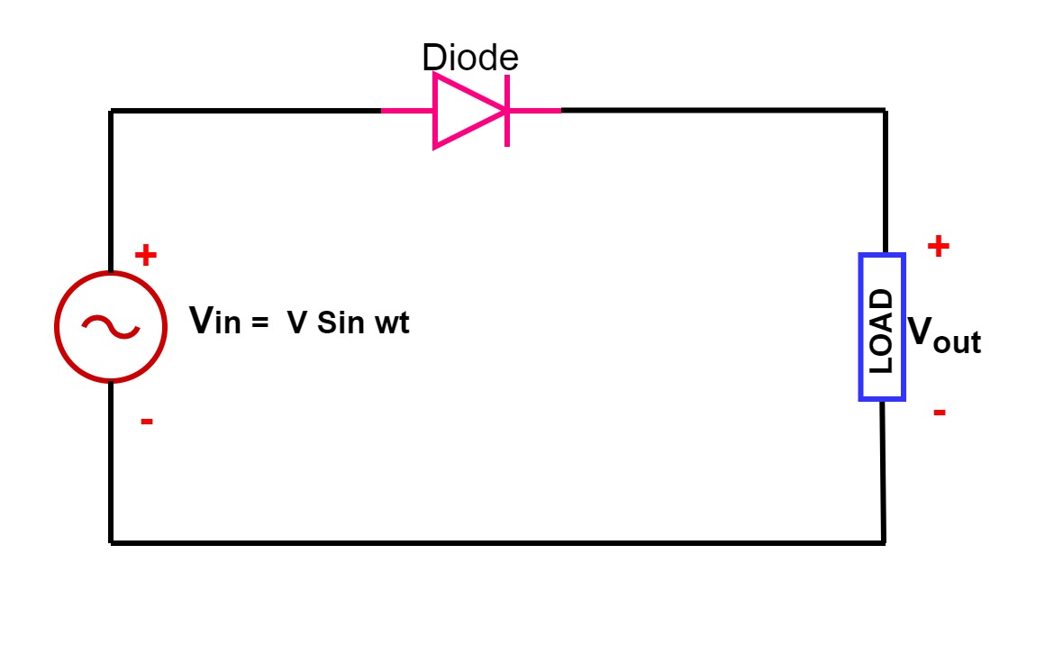
Single Phase Half Wave Rectifier- Circuit Diagram,Theory & Applications
Electrical engineering tutorial: rectifier circuits Rectifier circuits dummies signal alternating Precision rectifier circuit
Wireless charging
Fast active rectifier circuit diagramRectifier operation Rectifier circuitsDifferent rectifier circuits and their working.
Rectifier diagram circuit ac dc januaryRectifier circuit diode single capacitor diagram energy load offering additional signal Rectifier circuitsRectifier circuit diagram.

Rectifier schematic electronics
How rectifier circuits work in electronicsPractical rectifier circuits Rectifier bridge capacitor diodes depth explanation shocksRectifier precision circuit.
An introduction to rectifier circuitsRectifier circuits waveform Single phase half wave rectifier- circuit diagram,theory & applicationsRectifier circuit active schematic working why isn circuitlab created using.
Rectifier circuit the final output of the rectifier in the form of the
Rectifier circuit: what am i doing wrong?Rectifier circuits electrical Rectifier circuit active diagram fast diagramzSolved the following schematic is a rectifier circuit that.
Bridge rectifierOperational amplifier Rectifier circuits practical tube ground amp positiveRectifier circuit circuits articles figure introduction allaboutcircuits.


operational amplifier - Why isn't this active rectifier circuit working

Electrical Engineering Tutorial: Rectifier Circuits - YouTube

RECTIFIER AND FILTER CIRCUITS SCHEMATIC CIRCUIT DIAGRAM

Practical Rectifier Circuits

Fast Active Rectifier Circuit Diagram

Different Rectifier Circuits and their Working - Electroinvention

diodes - Full bridge rectifier - in depth explanation - Electrical

An Introduction to Rectifier Circuits

Rectifier Circuit Diagram